


1975_mini
-
Posts
2,581 -
Joined
-
Last visited
Content Type
Profiles
Forums
Events
Gallery
Store
Posts posted by 1975_mini
-
-
I have been slaking on my updates, but we have been making some good progress towards our St. Patty’s day goal of being back on the road.
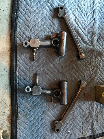
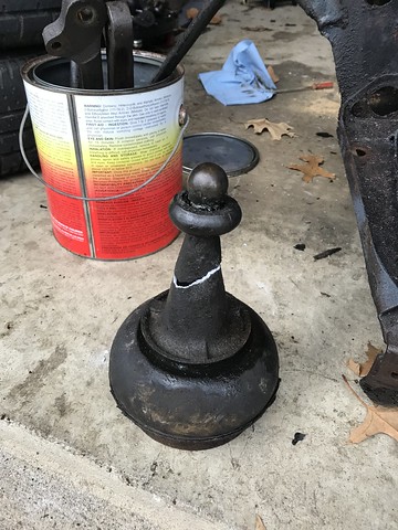
We left off with breaking down and cleaning the suspension components and the arrival of new parts. So let’s get those new shiny bits on the subframe and doing a few little upgrades. We will be making the suspension adjustable by replacing the fixed tie bars with adjustable ones, as well as the old aluminum trumpets with adjustable hi/low ones. Thanks to one trumpet breaking during disassembly. Here is the old next to the new.

Before I can start bolting goodies on to the subframe I needed to replace the bushings in the lower control arms. These fun little guys are tapered, fat in the middle narrow on the ends, think diamond shaped. This makes them a pain in the butt it get into the control arm, but I have just the toy for the job. A 5 ton press makes short work of it, this could be the best $50 I sent on craigslist awhile back. Once you use a press you question why you ever tried to beat bearings, bushings, etc… in with a hammer.
Now we are reading to build out the suspension, sense the subframe is out of the car I like to flip it upside down and let gravity hold cones and trumpets in the towers while I install the upper control arms. Work smarter not harder. First drop in the cone and then hi/low trumpet at the lowest setting to give plenty of to get the upper control arm in. The biggest pain with install the upper arm is keeping the washers and seals in place on either end while siding it in place. So you line it all up start sliding it in till a washer falls. The curse some, reset everything, and try again. It will take somewhere between 2 and 27 times to get it right. Once in place, it is as easy as sliding the pinion through, installing the retaining plate, and tightening the bolt on either end. Also a good idea to install the bolts on the bump stop before all this if you like your knuckles, or so I have heard.
Now for the lower control arm and tie bar. These are really easy, the lower arm is held in by a pin with a “D” head that you drive into the match hole in the subframe, and slap the bolt on the back. Lower arm in!! The tie rod is just as easy, with the only effort being getting the rubber bushing, poly bushing, and washers in the right order. Then bolt to the subframe and the control arm, repeat on the other side and you are ready to toss it back in the Mini.


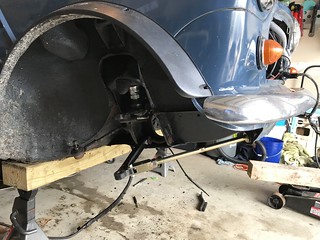
Let’s get the subframe back in Watson, this is a pretty straight forward process with most of the effort being in the preparation. You need to get the body up high enough to slide the subframe and jack under, while making sure your jack points a far enough back of the rear subframe mounting points. I like to use a 6 foot 2x6 I have laying around to spread the weight across the entire floor plan, I also prefer to jack out the rear of the Mini so it is still level. This makes the subframe go straight in rather than fighting the body and subframe at two different angles. ß Things you learn the hard way!!
With everything ready for the lift, I like to run a small board under the subframe so I can lift from a center point. This lets it come up evenly and, makes it easy to pivot. So you just start raising it slowly being sure not to snag any soft lines, pinch any hard lines, and get hung up on the body. Once you are about a half inch off the body start lining up you mounting points with the holes in the body, this is when having the central pivot point really helps. There are 10 mounting bolts, I start with the two in the top of each tower the bolts are long and you can get them starter while the subframe is still a half inch off the body. Getting these in helps center the subframe and once I have those 4 started I bring the subframe up to just touching the body and tighten those bolts till they are just touching the body. Not even hand tight as I will need a little wiggle to get the rest of the bolts. There are two rear bolts in each foot well, and one in either side of the front valiance. It just takes a little tweaking to get them all lined up, be sure to get them all started before tightening any of the down. Tighten them up and the subframe is in.
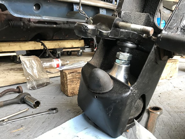
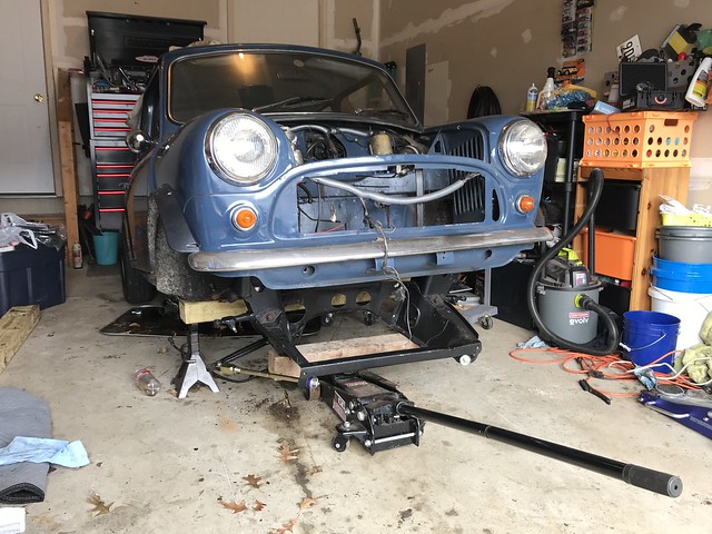
With the Subframe in, I tossed on the shocks, hubs, and wheels so I could ballpark in the hi/low trumpets. So Watson is sitting on all four wheels for the first time sense the project started.
-
A former member is selling his classic mini, and would love to see it go to someone in the area that would appreciate it and bring it back to its former glory.
Car has a Clean title, but is a re-VIN (as a 1972).
Because it is actually a 1992 it has SPI fuel injection, it is from the European market (Lefthand drive). The body, interior, and paint are in good condition. It has a modified ECU for power, but will include the original. The car has been previously wired for stereo with the speakers still in place, you would just need to add a head unit. Sound damping material has been added to decrease the road noise. There is some rust beginning to show in the floor plans. This is a great car for someone willing to turn some wrenches, and is not looking to drive someone else’s restoration project.
It has been sitting for 6 years, which has caused a few issues. Known Issues/work:
- Oil Pan Seal has perished
- Needs a new water pump
- Fabric sunroof locked closed (fabric shrunk and is too tight to allow the motor to release)
- Lucas electrical (horn and brights would only work occasionally)
- Rubber cones have collapsed.
Because of suspension and the fact it hasn't been driven in 6 years, please be prepared to pick it up with a trailer.
Asking $5k.
Pictures coming soon!!!!
For more information or if you have any questions, call Mike at 404-304-9382.
-
2 minutes ago, TGGRRR (Ali) said:
Are you going to change the date here? Do we need to RSVP again?
I just changed the date on the event, it did not clear out the RSVPs like the old web page. I will be emailing all on the yes and maybe list so they are aware of the change
-
10 hours ago, Sollestia said:
NOOOOOOOOOOOOOO
 . what about the 24th instead?!
  *Wiggles eyebrows*
I few folks have asked for the 24th, so I can make that work
-
 1
1
-
-
Ok, as of now the weather is saying snow from 1 to 3 inches (probably closer to one) smack during the run. So unfortunately we need to slide the run. Next Saturday the 23rd is saying 50 degrees, so we are going to slide to then.
Sorry for any inconvenience. I will change the date tomorrow and write everyone that has RSVPed to ensure all are aware of the change.
-
 1
1
-
-
The little bit of rain in the morning has shifted to snow in the forecast. I will be following the weather, and make a call once the forecast has solidified a little more. I will have an update by Thursday evening.
-
 2
2
-
2
-
-
The cell signal is non-existent still last year.
-
On 2/7/2019 at 12:23 PM, TGGRRR (Ali) said:
Make sure you have a hatchet/ chain saw for those sunrise runs
I signed up for the brewery run on Thursday, and the lake tour Friday.
-
1
-
-
26 minutes ago, TGGRRR (Ali) said:
Are they the same tires from the Dragon? They were screamers for sure
those are the ones, they definately have good thread life, they are good just really noisy
-
The route sheets have been added to the main post
-
1
-
-
2 minutes ago, TGGRRR (Ali) said:
I'm still on those stupid run flats but I can keep up!
so is Roxy, and they moan more than a pornstar!!
-
 1
1
-
-
4 hours ago, TGGRRR (Ali) said:
She's been on runs last summer. She's a beast!!!
Be careful what you wish for, remember Roxy is setting the pace, lol.
-
I am looking at the brewery run n Friday, and our DCMM on Saturday. Get some sunrise runs on the dragon Wednesday and Thursday. Other than that just going with the flow.
-
2 hours ago, TGGRRR (Ali) said:
Our couch spot is open, it's not a huge couch. The new cabin also has a utility room that is in the house, tiny room but would hold a single air mattress. I can't remember if it has a door or not. It's like a room that was built for the washer dryer that we don't have. It's off the living room and fully enclosed in the house.
If Ross doesn't take you up on it I will, it just me this year.
-
Just avoid the route of the ice cream and apple pie runs, as those two start after the photo
-
2
-
-
You can add me as a tie breaker, or whatever else you need. I am also right next to Glenn burnie
-
2
-
-
I made this last year for myself to get a better visual of what events are going when, and which ones conflict with each other. I have updated it for this year as the events appear now. I will check for changes and update as needed. Hope so other newer attendees find it helpful.
-
1
-
-
1 hour ago, ChrisTKD said:
Does anyone have a radio I could borrow? I misplaced all of mine during my last move.
I will have an extra
-
Brandy and I will sweep if you still need one
-
1
-
-
I am not missing prepaying for cobbler mountain like we did last year, right? Got my growler ready!
-
It has been a bit since my last update, I have been keeping busy with the boring stuff like cleaning and prepping parts and waiting on ordered parts to arrive.
So first came A LOT of elbow grease to get 40 plus years of road grime, grease, and rust off the upper and lower control arms as they will be reused in the manual subframe. So after several hours of degreaser, wire brushes, and a few other tricks we got back to bare metal. Here is an untouched upper control arm next to a cleaned one.
One down only three more pieces to go, but a few more hours and we got there
Now that all the parts are clean it was time to mask off surfaces and get a coat of gloss black chassis paint on them, pretty happy with the way they came out.
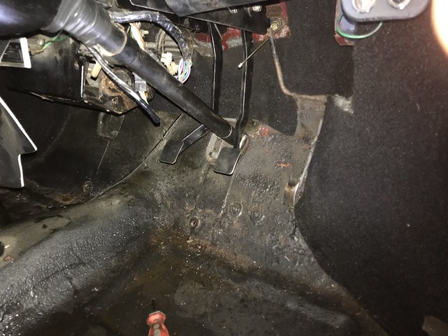
I hit the clutch/brake pedal box with a new coat of paint, and decided I was tired of braking things down and was ready to put something back. The space is a bit tight, but with a little spatial reasoning I was able to work the pedals around the steering column and into place. That’s right, Watson is officially living the three pedal life.
I also ran into my first unexpected problem in the project. I needed to separate the trumpets from the rubber cones. The trumpet has a lip that sits inside the rubber cone, this creates a lot of surface area for the two to rust weld together over the years. Think or the hub centric wheels you have battle with getting off and that was only a few years. So then you have a cone on one side and a half sphere on the other, not my top two picks for shapes to get a grip on. This was not the unexpected problem, I knew this was coming. The surprise came as I was looking at one of the trumpets and saw a hair line crack, I gave it a frim wack with the rubber mallet and SURPRISE it broke right off.
I had been debating upgrading to adjustable hi/low trumpets, but had decided to hold off. Watson’s had a different plan so upgrade it is.
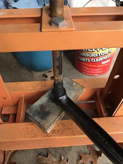
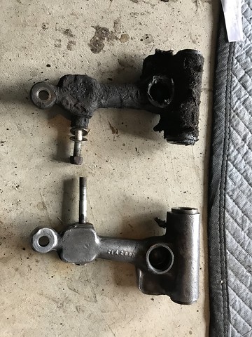
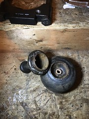
So I still had to get the one broken trumpet and the one still good trumpet out of the cones. So it was time to come up with a Rube Goldberg machine. I decide that a combination of a large bearing separator, three clawed puller, crowbar, rubber mallet, and some PB blast should get the job done. So here was the plan use the bearing separator to create a gap, this worked well tightening the separator created about a 1/8” gap. I loosened the separator and use the new gap to get PB blast into the collar. I let is do its magic for about an hour, then tightened the separator in past the edge of the trumpet so I could use it to pull. I attached the puller to the edges of the separator and began to add pressure. You could hear it making all those fun creaking noises, and I would give it a few taps with the mallet. A few turns on the puller, and back an fourth. Sorry no photos of the process as I was more focused on not snapping the trumpet and sending metal flying in all directions. Finally they let go and there was no bodily harm. Here are the tools used and the final result.
So at this point I was at the mercy of the shipping guy waiting on parts (this was a whole another debacle) so I spend my snow day straightening the garage and tidying up some little things while running to the garage door every time a heard a truck hoping it would be the delivery guy. No Luck
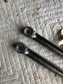
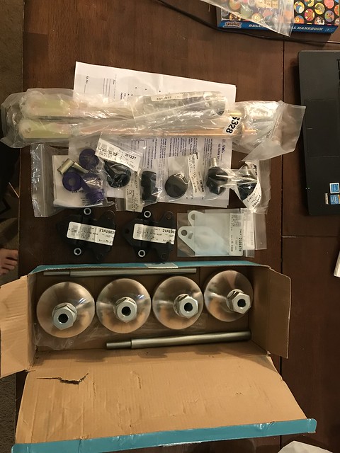
Final this Thursday the parts box arrived with Hi/low trumpets, new tie rods (the old one made Elton John look straight), and a bunch of new bushings and seals for the suspension components. Hey @Gearhead60 check out those engine mounts with built in nutserts!!
So the goal over the long weekend is to get the subframe back together and into Watson. We are moving in the right direction now.
-
1
-
-
On 1/12/2019 at 10:11 PM, Revwillie said:
I had a burned out fog lamp and I've been trying different LED color bulbs.
Found a cheap pair of yellow H11 bulbs but they didn't look right.
I'm very happy with a pair of dual-mode H11 bulbs from ebay. They are bright white but if you turn them off and back on again, they are "ice" blue. I'm trying to figure out how to take a good picture or video.
Look forward to seeing them
-
These would be great for anyone looking for a set of rims for winter tires. Just saying.
-
1
-
-
We will bring baked Mac ‘n’ cheese


Oh Shift!!! Watson is going Manual.
in Maintenance & Modifications
Posted
With Watson now sitting on all four and the subframe back in place it is time for some big leaps forward in this project. Before some big things I went ahead and rerouted the battery cable replumbed the brakes just to get them out of the way while the engine bay was nice and open. Before we could go any farther forward there was one last decision to be made. Watson old automatic setup used a hardy spider (universal joint) to connect the axels to the differential, but the new manual trans setup uses pot joint (CV style) setup. Option one is pull the input shafts from the diff and order new output covers to allow me to use the Hardy spider setup and my existing axels. Option two is leave the diff setup on the manual transmission and instead get pot joint and new axels and switch my hubs over to them. After talking to some classic Mini folks that were basically split down the middle, it was what was most cost effective.
Then I remember where I might be able to get some pot joints and the right axels. Which lead to the next step to get Watson closer to the road was not actually on Watson, but instead @IndiCooper Celia's Clubman “The Duck”. Here’s a photo for those that haven’t seen a classic clubman or specifically the Duck, words do not do it justice.
When I pulled the motor and other little things for Watson I pulled the disc brake setup for Celia to replace the old front drum setup on Duck. So I reached out to her about getting the old pot joints and axels off the duck which got me helping out with Duck’s conversion. After a day of fighting stuck bolts and a few bent parts, duck was sporting some fresh “PINK” disc brakes and I had the pot joints and axels I needed. That’s right Watson is going to have some Duck in him!!!
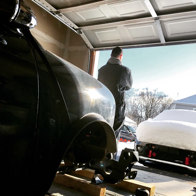
So now I have all the major components to finish the project, while limiting cost overages and Brandy killing me. So the next step on the list requires THIS. That’s right an engine hoist, THE ENGINE IS GOING IN!!!!
I went to toss on the new motor mounts with those captive nuts before installing the engine. Just three bolt on each side a quick five minute project, or so I thought until I saw this. On the radiator side the mount was held on by one sharpened bolt and a cross threaded stud insert. I think this was a result of the annoy nut and bolt combo (read about that adventure above) that attach mounts to the subframe. What I thing happened was the last person to put this engine in the white Mini decided to install the mounts to the subframe first then lower the engine on to them because those bolts go into threaded holes so no fighting with blind nuts. Well they obviously could not get thing lined up, so they created a point on one bolt to make it easier to start hoping it would line everything up. It definitely didn’t hence they gave up on bolt two and cross threaded a smaller stud, and then realized the bottom nut is completely inaccessible. Always fun to see what others think is good enough. So I now have to remove the bracket as it was a bit rustier than I would like and I need to get the cross threaded stud out. So I drilled out the stud, the threads were not destroyed so ran a tap through them to clean them up. Grinded it down and a fresh coat of paint. So what should have been five minutes took an hour, but now it is right.
Dropping in the engine is pretty straight forward. I use the head stud next to the thermostat and the manifold stud on the opposite corner as pickup points. The engine is pretty vertical so it goes straight down, you just have to pull the engine a bit forward to allow the two bolts on the back of the diff to clear the lip of the subframe. Only two things to remember are to attach the speedo cable before lowering the engine as it is a pain once its in place and once half way down attached the ground strap to the bottom of the bell housing. Once the engine mounts are hovering over the subframe holes start the two bolts on each side, this takes a little ballet with to hoist to get them all lined up. Sorry for no photos going in, but kind of had my hands full lowering it in.
With to engine in its time to mate up a shifter so we can grab some gears. This is a pretty simple process, with the shifter linkage and shifter in one unit. You feed the shifter up from underneath the car, the holes are different for the manual and auto mounts, but the floors are universal to both holes are there, WIN. For the manual there are two studs at the rear with bushings, feed the studs thought the holes and slap a nut on them and it is that easy. I used a floor jack to raise the unit and support it from below while I put on the bolts, just makes life easier. For mating the linkage to the transmission is just as easy, with the system consisting of two rods. The top has a yoke on the end and is held by a nut and bolt through a bushing in the transmission housing. The bottom can be a pain if you haven’t done it before the rod has a pivoting collar on the end that goes over the selector shaft coming out the back of the transmission. The tricky part is holes in the collar and shaft that have to be aligned and a pin driven through. I use a punch that is smaller than the hole to get the holes lined up, then slide out the punch and hammer in the pin. It is a bit tight so a small wood working hammer works well as you do not need a lot of force to hammer the pin in. So the shifter is in and mated to the transmission, I may have took a minute to grab a few gears just you make sure everything was working properly.
The hole will be covered by a rubber boot, it’s currently on a slow boat from England. You also may notice I do not have a gear knob, so I am open to suggestion?
So we are get towards to bottom of the check list. What is left?
- Switch over outer CV joints to new axels
- Install axels
- Wire engine
- Replace some fuel lines
- Install manifold and carburetor
- Install exhaust
- Bleed clutch
- Add oil and coolant
- See if it starts!!!